×
- Live Chat
- 1-888-726-6993

My Garage
My Account
Cart
Genuine Nissan Maxima Axle Beam
Rigid Axle- Select Vehicle by Model
- Select Vehicle by VIN
Select Vehicle by Model
orMake
Model
Year
Select Vehicle by VIN
For the most accurate results, select vehicle by your VIN (Vehicle Identification Number).
9 Axle Beams found
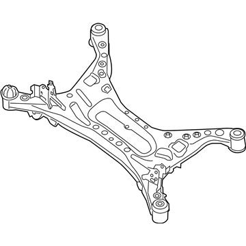
Nissan Maxima Member Compl-Rear Suspension
Part Number: 55400-4RA2C$626.59 MSRP: $863.07You Save: $236.48 (28%)Ships in 1-3 Business DaysNissan Maxima Beam Complete-Rear Suspension
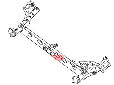
Part Number: 55501-43U01$860.95 MSRP: $1103.78Limited AvailabilityYou Save: $242.83 (22%)Nissan Maxima Beam Complete-Rear Suspension
Part Number: 55501-31U01$860.95 MSRP: $1103.78Limited AvailabilityYou Save: $242.83 (22%)
Nissan Maxima Axle Beam
If you need any OEM Nissan Maxima Axle Beam, feel free to choose them out of our huge selection of genuine Nissan Maxima Axle Beam. All our parts are offered at unbeatable prices and are supported by the manufacturer's warranty. In addition, we offer quick shipping to have your parts delivered to your door step in a matter of days.
Nissan Maxima Axle Beam Parts Questions & Experts Answers
- Q: How do you properly remove and reinstall the Axle Beam and Lateral Link on Nissan Maxima?A: Loosen the wheel lug nuts, raise the vehicle, and support it securely on jack stands before removing the wheels. For vehicles equipped with an Anti-lock Brake System (ABS), remove the rear wheel speed sensors and detach the speed sensor wiring harness by removing the clamp bracket bolt. Disconnect the parking brake cables, then remove the brake calipers and brake discs, hanging the calipers with lengths of wire from the coil springs. If replacing the axle assembly, remove the rear hub and wheel bearing assemblies. Place a floor jack underneath the center of the rear axle assembly, ensuring it doesn't contact the lateral link, and raise the jack just enough to support the axle assembly; if two floor jacks are available, place one at each end of the axle beam. Unbolt the lower ends of the Shock Absorbers from the axle, then disconnect the lateral link from the chassis by removing the nut and bolt. Remove the pivot bolts for the Trailing Arms, and with assistance to balance the axle assembly, carefully lower the axle/lateral link assembly on the jack. Check the condition of the lateral link, control rod, and trailing arm bushings, replacing any that are deteriorated. The lateral link and control rod can be removed from the axle beam by removing the fasteners and sliding the assembly off the pin on the axle; during reassembly, ensure the arrow on the lateral link points up and that the control rod bushing with the smaller diameter hole is connected to the lateral link. Installation follows the reverse order of removal, ensuring all suspension fasteners are tightened to the specified torque. The lateral link and shock absorber fasteners should be tightened with the suspension at normal ride height, which can be simulated by raising the rear suspension with a floor jack, while the trailing arm pivot bolts should be tightened with the rear suspension in the unloaded position. Finally, tighten the brake fasteners to the specified torque, install the wheels and lug nuts, lower the vehicle, and tighten the lug nuts to the specified torque.


