×
- Live Chat
- 1-888-726-6993
My Garage
My Account
Cart
Genuine Nissan Quest MAP Sensor
Manifold Air Pressure Sensor- Select Vehicle by Model
- Select Vehicle by VIN
Select Vehicle by Model
orMake
Model
Year
Select Vehicle by VIN
For the most accurate results, select vehicle by your VIN (Vehicle Identification Number).
6 MAP Sensors found
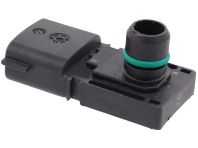
Nissan Quest Evap Control System Pressure Sensor
Part Number: 22365-AM60A$171.52 MSRP: $260.90You Save: $89.38 (35%)Ships in 1-3 Business Days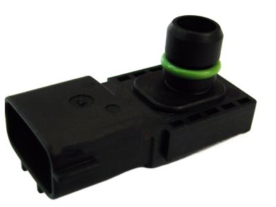


Nissan Quest Sensor-Boost
Part Number: 22365-JA10B$171.52 MSRP: $260.90You Save: $89.38 (35%)Ships in 1-2 Business Days
Nissan Quest Sensor-Boost
Part Number: 22365-1TV0B$171.52 MSRP: $260.90You Save: $89.38 (35%)Ships in 1-3 Business Days
Nissan Quest Boost Sensor
Part Number: 25085-6B700$243.51 MSRP: $335.42Limited AvailabilityYou Save: $91.91 (28%)
Nissan Quest MAP Sensor
If you need any OEM Nissan Quest MAP Sensor, feel free to choose them out of our huge selection of genuine Nissan Quest MAP Sensor. All our parts are offered at unbeatable prices and are supported by the manufacturer's warranty. In addition, we offer quick shipping to have your parts delivered to your door step in a matter of days.
Nissan Quest MAP Sensor Parts Questions & Experts Answers
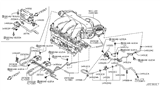
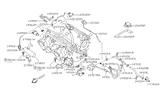
- Q: What is the function and testing procedure of the Manifold Absolute Pressure (MAP) sensor and its solenoid valve on Nissan Quest?A: MAP sensor is utilized with MAP sensor solenoid valve, which is used for intake manifold pressure, and ambient barometric pressure change circuits based on the variations in the engine load and speed. The PCM uses the signal from the MAP sensor to control the Evaporative emissions, where by applying voltage to the solenoid valve it changes the vacuum signal for measuring the ambient pressure and where removing voltage enables measurement of intake manifold pressure. The vacuum signal is converted into voltage by the MAP sensor and the voltage ranges between 0.5v which is the closed throttle voltage to about 5.0v which is the wide open throttle voltage though the voltage varies slightly with changes in altitude. Each is installed on the cowl in the engine compartment and the EEC will sense numerous problems with the MAP sensor setting codes for certain problems. To check the reference voltage from the PCM to the MAP, remove the MAP harness connector and place meter probes on the REF terminal you should a battery voltage with the ignition key ON about 5.0 volts. In case of no reference voltage it shows short or open circuit to the PCM or defective PCM may be there. Next, without starting the engine:-Unplug the vacuum from the sensor-If you've collected the MAP sensor-connector, read the voltage on SIG terminal, it should be 3.2 to 4.8 volts. After reconnecting the vacuum hose, s to the engine and examine the voltage on the signal wire which should increase with the increase in RPMs and decrease to below 2.0 volts at idle. If signal voltage remains the same, look for vacuum from solenoid valve; if vacuum is present after 5 sec of engine start and MAP sensor receives REF signal, replace MAP sensor. If vacuum is not present examine the condition of the hoses, if the hoses seem to be in good condition then measure battery voltage at the solenoid valve with ignition on. If voltage is absent, check the wiring harness; if present, change solenoid valve, and recheck. For replacement, the negative battery terminal must be removed and the electrical connector which is attached to the MAP sensor or solenoid valve severed from the main body, the retaining nut/bolt must also be loosened before the couplings are removed. Installation, on the other hand, begins at the bottom of the utility pathway and goes in the opposite order of the removal procedure.
Related Nissan Quest Parts
 Nissan Quest Camshaft Position Sensor
 Nissan Quest Crankshaft Position Sensor
 Nissan Quest Oxygen Sensor
 Nissan Quest Mass Air Flow Sensor
 Nissan Quest Coolant Temperature Sensor
 Nissan Quest Knock Sensor
 Nissan Quest Vehicle Speed Sensor
 Nissan Quest Throttle Position Sensor
 Nissan Quest Automatic Transmission Shift Position Sensor Switch
 Nissan Quest Parking Assist Distance Sensor
Browse by Year
2017 MAP Sensor 2016 MAP Sensor 2015 MAP Sensor 2014 MAP Sensor 2013 MAP Sensor 2012 MAP Sensor 2011 MAP Sensor 2010 MAP Sensor 2009 MAP Sensor 2008 MAP Sensor 2007 MAP Sensor 2006 MAP Sensor 2005 MAP Sensor 2004 MAP Sensor 2003 MAP Sensor 2002 MAP Sensor 2001 MAP Sensor 2000 MAP Sensor 1999 MAP Sensor 1998 MAP Sensor 1997 MAP Sensor