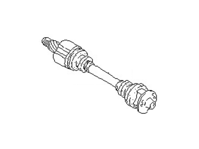
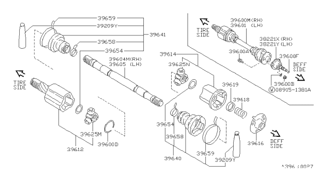
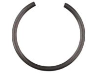
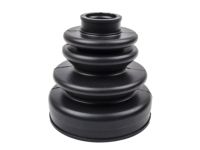
Part fixing of the axle shafts calls for the use of a tool for the alignment of the splines and this tool is referred to as the Kent Moore tool Number J/34296 and J/34297. To start with, chock the wheels, lift the front of the vehicle and sustain with jackstands, unbolt and withdraw the wheel and brake caliper assembly though retaining the brake hose. Again, be careful not to depress the brake pedal. Take out the cotter pin and wheel bearing lock nut; to avoid scratching the boots as you take off the axle shaft, cover them with a shop towel. To disassemble the car and free up space for a repair, pull the axle shaft from the steering knuckle using a block of wood and a mallet; to free up more space, you might have to partially remove the strut mounting bolts on the car. Take out the tie rod ball joint removing the nut and the cotter pin, for reassembly use a new nut and cotter pin. If your model comes with a manual transaxle, then tap the right side inner CV-joint out of the transaxle case. Without any support bracket installed, support the engine under the oil pan, and then the support bearing bracket must be the next to be removed before pulling the right axle shaft. Look at part 4, it explains how for manual transaxle models pry the left CV-joint inner flange out of the transaxle case and if needed, take the shaft out of the steering knuckle. For the automatic transaxle models, a dowel should be passed through the right side axle shaft hole and the left axle shaft has to be tapped out. Before fitting the shafts, replace the old oil seal with a new one and use an alignment tool in putting the axle shaft into the transaxle; lock the axle shaft by aligning the serrated shafts and removing the tool. With the side gear still in that position push forward the axle shaft and install the circular clip into the axle shaft by pressing it in as far as it would go. The support bearing bracket retaining bolts should then be put in place and the axle shaft inserted into the steering knuckle, while any strut mounting bolts that have been loosened should be tightened again. Reinstall the tie rod end with an appropriate nut and cotter pin; also, the new caliper assembly as well as the wheel bearing locknut should be fitted, tightened to 174-231 ft. lbs. Replace a cotter pin in the wheel hub and the wheel, and also flush the brake system if it is necessary before performing a road test on the car. When operating the CV-joint overhaul just remove the axle shaft and then secure it in a protected jaw vise, next step is to relieve the boot bands and then it is required to mark both the slide joint housing and the spider assembly for proper alignment. Disassembly of the slide joint: first and foremost, the slide joint housing, then the spider snapring, and finally the spider assembly repairing from the axle shaft, and before that, have to put some tape on the driveshaft splined so that the CV-boot would not be damaged. The following are the proper procedures; The new CV-boot shall be installed together with a new boot band, the spider assembly should be installed in such a way that match marks are properly lined up, a new spider snapring should also be installed. Apply the correct grease onto the CV-boot and the rest of the boot bands can then be fitted onto the corresponding CV-shaft. As for the wheel side, proceed with the same steps as before, successfully untwisting the structure, and you might require a puller to extract the joint assembly, which must be replaced if it is damaged. Tape over the splined end of the axle shaft, then locate a source of fresh axle shaft lubricant, preferably with an open package of CV-boot if possible, fit the CV-boot with a new boot band. Gently lower the joint assembly into position to not damage the threads of the axle nut, and make sure match marks on the parts are in the same positions. Place an appropriate amount of grease in the CV-boot and fit the remaining number of boot bands and then twist and crimp them using an appropriate tool.
Posted by NissanPartsDeal Specialist 
