×
- Live Chat
- 1-888-726-6993

My Garage
My Account
Cart
Genuine Nissan 350Z Crankshaft
Crank Shaft- Select Vehicle by Model
- Select Vehicle by VIN
Select Vehicle by Model
orMake
Model
Year
Select Vehicle by VIN
For the most accurate results, select vehicle by your VIN (Vehicle Identification Number).
4 Crankshafts found
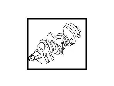
Nissan 350Z CRANKSHAFT Assembly
Part Number: 12200-JK21A$1581.36 MSRP: $1882.57You Save: $301.21 (16%)Ships in 1-3 Business DaysNissan 350Z CRANKSHAFT Assembly
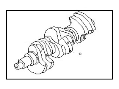
Part Number: 12200-JK20A$1581.36 MSRP: $1882.57You Save: $301.21 (16%)Ships in 1-3 Business Days
Nissan 350Z Crankshaft
If you need any OEM Nissan 350Z Crankshaft, feel free to choose them out of our huge selection of genuine Nissan 350Z Crankshaft. All our parts are offered at unbeatable prices and are supported by the manufacturer's warranty. In addition, we offer quick shipping to have your parts delivered to your door step in a matter of days.
Nissan 350Z Crankshaft Parts Questions & Experts Answers
- Q: How can the crankshaft be removed and reinstalled in an engine on Nissan 350Z?A: In the following scenario, once the engine is extracted from the vehicle, and provided that the flywheel, crankshaft pulley, timing chain, oil pan, oil pump, oil filter, piston-connecting rod assemblies have been disassembled from the crankshaft, the latter can be successfully removed. Place the dial on the crankshaft and take a pre-removal dimension of end play on the crankshaft. Connect the indicator to the crankshaft, pry the crankshaft to the rear, set zero on the indicator than pry the crankshaft to the front and which should read between 0.003 and 0.010 inch. If it lies outside this range, and the thrust washer/bearing assembly used with it is worn, do not use the endplay setting as an indication. Starting from (via loosing it), turn the main bearing cap/bedplate bolts to such a stage that they can be removed manually and use a soft-face hammer to remove the assembly from the cylinder block. Slowly raise the crankshaft out, preferably with help because it should be rather heavy. Installation of the main bearing cap assembly of the engine should be done and placed at the front part with the arrow facing frontwards. For installation, it is advisable to have clean engine block as well as crankshaft with an inspection. Place the block with its bottom upwards, take off the main bearing cap assembly, and clean up the bearing seats. Will be fitted in the block and new upper main bearing inserts oil hole will align to the required one while lower inserts will be placed in the main bearing cap. What has to be stressed at this point is that no hammering is to be done on the inserts, and no lubrication must be applied as well. Scrub and degrease the crankshaft and bearing surfaces and using the engines width, lay the crankshaft in position with thrust washers either side of journal #3. Check and verify the oil clearance of the main bearing through the use of Plastigage and guarantee the position of the oil holes for the bearings and those of the caps. Once the bolts are tightened, the caps are to be unscrewed and the Plastigage width is read against the scale to get clearance which should range between 0.0015 to 0.0023 inch. If the clearance is incorrect ensure that no debris was present during the measurement process and if actually rolling-element bearings were being measured, then the bearing inserts may need to be replaced. Next, wipe off any Plastigage that may have stuck to the journals and insert faces which are followed by applying a film of grease or assembly lube on the bearing surfaces and then re-fitting the crankshaft. Make sure the journals are free from any debris and that a lubricant layer is applied on the faces of the bearing insert, and the thrust washers. For those models, which have a bedplate, it is necessary to put the RTV sealant to the sealing area before the putting on of the main bearing caps or bedplate. Loosen the bolts slightly, further tighten the bolts to the crankshaft torque and then take the crankshaft end play again. Twist the crankshaft to discover if has any interference; the crankshaft should be able to turn freely with a running torque of 50 in-lbs or less and then fit a new rear main oil seal.


